Ammeter Circuit Diagram - Electrical Meters : Use an ammeter and voltmeter to take readings in circuits.. Unlike a block diagram or layout diagram, a circuit diagram shows the actual electrical connections. A circuit diagram (electrical diagram, elementary diagram, electronic schematic) is a graphical representation of an electrical circuit. View the circuit as a schematic diagram, or switch to a lifelike view. Ammeter ranges are created by adding parallel shunt resistors to the movement circuit, providing a precise current division. Circuit diagram is a free application for making electronic circuit diagrams and exporting them as images.
Circuit symbols are used in circuit diagrams showing how a circuit is connected together. I think by using a current sensor (readily available in market ) you can construct your arduino based ammeter. A circuit diagram (electrical diagram, elementary diagram, electronic schematic) is a graphical representation of an electrical circuit. The meter is generally used for measuring the particular quantity. In the electric circuit diagram at right, possible locations of an ammeter and a voltmeter are question:
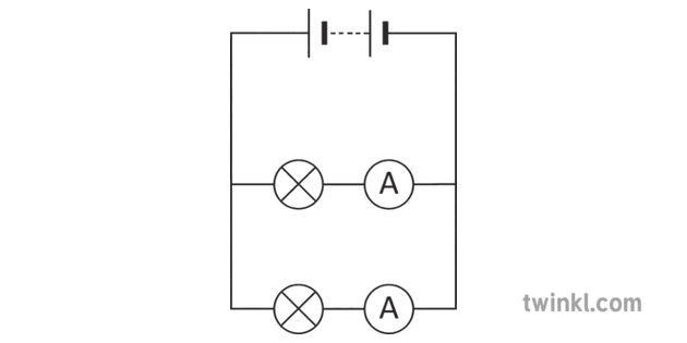
Parallel Circuit With Ammeters Science Circuit Symbols Scientific Diagram from images.twinkl.co.uk Diagram of a simple circuit with one resistor, is the ammeter correctly integrated into the circuit? This is the ammeter symbol. To build a circuit you need a different diagram showing the layout of the parts on breadboard (for temporary. This free circuit diagram software lets you export circuit diagrams to png and svg file formats. Voltmeters and ammeters are used to measure voltage and current, respectively. The complete circuit diagram of this digital ammeter project is shown in the image below. Meter is an instrument which can measure a particular quantity. The construction of ammeter can be done in two ways like series and the following circuit represents the basic circuit diagram and the connection of the ammeter circuit.
The meter is generally used for measuring the particular quantity.
Meter is an instrument which can measure a particular quantity. Explain basic electricity relationships in series and parallel circuits. In the electric circuit diagram at right, possible locations of an ammeter and a voltmeter are question: Circuit diagram is a free application for making electronic circuit diagrams and exporting them as images. .of a simple circuit with one resistor, is the ammeter correctly integrated into the circuit? String led circuit diagram constant current power supply. Which circuit diagram below correctly shows the connection of ammeter a and. Here's another classic diy effects. An ammeter and a voltmeter are connected as follows: Introduction of ammeter as we know a word meter is associated with the measurement system. It is used to measure the current passing at a particular point. I think by using a current sensor (readily available in market ) you can construct your arduino based ammeter. The complete digital current meter circuit works on +5v which is regulated by a 7805 voltage regulator.
.of a simple circuit with one resistor, is the ammeter correctly integrated into the circuit? Here we will discuss both with ammeter and voltmeter circuit diagram. The complete circuit diagram of this digital ammeter project is shown in the image below. The circuit diagram of the bridge rectifier elements is shown in the figure below. View the circuit as a schematic diagram, or switch to a lifelike view.
Voltmeter Ammeter from www.electronics-diy.com Circuit diagrams are a pictorial way of showing circuits. The circuit diagram of the bridge rectifier elements is shown in the figure below. Design circuits online in your browser or using the desktop application. Circuit diagram is a free application for making electronic circuit diagrams and exporting them as images. View the circuit as a schematic diagram, or switch to a lifelike view. Ammeter ranges are created by adding parallel shunt resistors to the movement circuit, providing a precise current division. The proposed digital voltmeter, ammeter circuit module can be effectively used with a power supply referring to the circuit diagram below, the 3 digit digital display module is build through the ics ca. An ammeter measures current and a voltmeter measures a potential difference.
Electricians and engineers draw circuit diagrams to help them design the actual circuits.
Some materials have low resistance and are conductors; It is used to measure the current passing at a particular point. View the circuit as a schematic diagram, or switch to a lifelike view. I think by using a current sensor (readily available in market ) you can construct your arduino based ammeter. Explain basic electricity relationships in series and parallel circuits. The complete circuit diagram of this digital ammeter project is shown in the image below. The meter is generally used for measuring the particular quantity. Circuit symbols are used in circuit diagrams showing how a circuit is connected together. In dc moving coil instrument the. In the electric circuit diagram at right, possible locations of an ammeter and a voltmeter are question: Circuit diagrams are a pictorial way of showing circuits. Diagram of a simple circuit with one resistor, is the ammeter correctly integrated into the circuit? Unlike a block diagram or layout diagram, a circuit diagram shows the actual electrical connections.
View the circuit as a schematic diagram, or switch to a lifelike view. The circuit diagram of the bridge rectifier elements is shown in the figure below. An ammeter measures current and a voltmeter measures a potential difference. Digital ammeter circuit diagram and complete project using pic16f877a microcontroller, program of in this digital ammeter circuit project, 0.47 ohm shunt resistor is used. Which circuit diagram below correctly shows the connection of ammeter a and.
The Circuit Digital Volt And Ampere Meter Circuit Diagram from 4.bp.blogspot.com Ad by forge of empires. An ammeter measures current and a voltmeter measures a potential difference. The circuit diagram of multi range dc ammeter is shown in below figure. It is used to measure the current passing at a particular point. Use an ammeter and voltmeter to take readings in circuits. The schematic diagram shows the connection of the arduino uno with lcd, resistor and led. All circuit symbols are in standard format and they are mostly used to draw a circuit diagram and are standardized internationally by the ieee. The construction of ammeter can be done in two ways like series and the following circuit represents the basic circuit diagram and the connection of the ammeter circuit.
An ammeter and a voltmeter are connected as follows:
String led circuit diagram constant current power supply. An ammeter measures current and a voltmeter measures a potential difference. The complete digital current meter circuit works on +5v which is regulated by a 7805 voltage regulator. The circuit diagram of the bridge rectifier elements is shown in the figure below. Ad by forge of empires. In the electric circuit diagram at right, possible locations of an ammeter and a voltmeter are question: Some materials have low resistance and are conductors; View the circuit as a schematic diagram, or switch to a lifelike view. Here's another classic diy effects. Electricians and engineers draw circuit diagrams to help them design the actual circuits. Which circuit diagram below correctly shows the connection of ammeter a and. The complete circuit diagram of this digital ammeter project is shown in the image below. Digital ammeter circuit diagram and complete project using pic16f877a microcontroller, program of in this digital ammeter circuit project, 0.47 ohm shunt resistor is used.